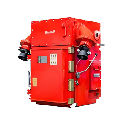
Smart Prefabricated Compact Transformer Station
Key attributes
| Brand | ROCKWILL |
| Model NO. | Smart Prefabricated Compact Transformer Station |
| Rated frequency | 50Hz |
| Maximum LV AC Inputs | 17kV |
| Series | YBS |
Description
The Smart Transformer Station is a core component of modern power systems, combining advanced sensing, communication, computing, and automation. Its primary equipment performs real-time self-diagnostics, while the secondary system employs a fully digital and networked architecture.
By enabling data-driven monitoring, predictive fault analysis, and automatic control, the station enhances grid stability, boosts overall efficiency, reduces operational costs, and drives the industry’s green, intelligent evolution.
Key Features
-
Simplicity and Convenience: The Smart Transformer Station features simple structure, easy installation and convenient daily maintenance.
-
High Efficiency and Energy Saving: The Transformer Station adopts optimized design to lower energy loss and achieve outstanding energy-saving performance.
-
Intelligence and Advancement: Built-in intelligent monitoring system makes the Smart Transformer Station realize automatic operation, fault early warning and remote management.
-
Reliability and Durability: The Transformer Station adopts high-quality materials and strict manufacturing process, ensuring stable performance and long service life.
Technology parameters
YBS-3400
| Category | Item | Specification |
|---|---|---|
| Input |
Maximum LV AC Inputs | 17 |
| AC Power | 3,400 kVA | |
| Rated Input Voltage | 800 V | |
| LV Main Switches | ACB (2,900 A / 800 V / 3P, 1 pcs), MCCB (250 A / 800 V / 3P, 17 pcs) | |
| Output |
Rated Output Voltage | 11 kV, 13.8 kV, 15 kV, 20 kV, 22 kV, 30 kV, 33 kV, 34.5 kV, 35 kV |
| Frequency | 50 Hz / 60 Hz | |
| Transformer Type | Oil-immersed, Conservator Type | |
| Transformer Cooling Type | ONAN | |
| Transformer Tappings | ±2 x 2.5% | |
| Transformer Oil Type | Mineral Oil (PCB-Free) | |
| Transformer Vector Group | Dy11 | |
| Transformer Min. Peak Efficiency Index | Tier 1 or Tier 2 in Accordance with EN 50588-1 | |
| RMU Type | SF6 Gas Insulated | |
| RMU Transformer Protection Unit | MV Vacuum Circuit Breaker Unit | |
| RMU Cable Incoming / Outgoing Unit | Direct Cable Unit or Cable Load Break Switch Unit | |
| Auxiliary Transformer | Dry Type Transformer, 5 kVA, Dyn11 | |
| Output Voltage of Auxiliary Transformer | 400 / 230 Vac or 220 / 127 Vac | |
| Protection |
Transformer Monitoring & Protection | Oil Level, Oil Temperature, Oil Pressure and Buchholz |
| Protection Degree of MV & LV Room | IP 54 | |
| Internal Arcing Fault Classification of YBS | IAC-A 20kA/1s | |
| MV Relay Protection | 50/51, 50N/51N; Type I+II | |
| Anti-rodent Protection | C5 Medium in accordance with ISO 12944 | |
| Features |
2 kVA UPS | Optional |
| MV Surge Arrester for MV VCB | Optional | |
| General |
Dimensions (W x H x D) | 6,058 x 2,896 x 2,438 mm (20' HC Container) |
| Weight | < 15 t | |
| Operating Temperature Range | -25℃ ~ 60℃ | |
| Relative Humidity | 0% ~ 95% | |
| Max. Operating Altitude | 1,000 m / 1,500 m | |
| MV-LV AC Connections | Prewired and Pretested, No Internal Cabling Onsite | |
| LV & MV Room Cooling | Smart Cooling without Air-across for Higher Availability | |
| Communication | Modbus-RTU, Preconfigured with Smartlogger3000B | |
| Applicable Standards | IEC 62271-202:2022, EN 50588-1, IEC 60076-1, IEC 62271-200, IEC 61439-1 |
YBS-6800
| Category | Item | Specification |
|---|---|---|
| Input |
Maximum LV AC Inputs | 34 |
| AC Power | 6,800 kVA | |
| Rated Input Voltage | 800 V | |
| LV Main Switches | ACB (2,900 A / 800 V / 3P, 2×1 pcs), MCCB (250 A / 800 V / 3P, 2×17 pcs) | |
| Output |
Rated Output Voltage | 11 kV, 13.8 kV, 15 kV, 20 kV, 22 kV, 30 kV, 33 kV, 34.5 kV, 35 kV |
| Frequency | 50 Hz / 60 Hz | |
| Transformer Type | Oil-immersed, Conservator Type | |
| Transformer Cooling Type | ONAN | |
| Transformer Tappings | ±2×2.5% | |
| Transformer Oil Type | Mineral Oil (PCB-Free) | |
| Transformer Vector Group | Dy11-y11 | |
| Transformer Min. Peak Efficiency Index | Tier 1 or Tier 2 In Accordance with EN 50588-1 | |
| RMU Type | SF6 Gas Insulated | |
| RMU Transformer Protection Unit | MV Vacuum Circuit Breaker Unit | |
| RMU Cable Incoming / Outgoing Unit | Direct Cable Unit or Cable Load Break Switch Unit | |
| Auxiliary Transformer | Dry Type Transformer, 5 kVA, Dyn11 | |
| Output Voltage of Auxiliary Transformer | 400 / 230 Vac or 220 / 127 Vac | |
| Protection |
Transformer Monitoring & Protection | Oil Level, Oil Temperature, Oil Pressure and Buchholz |
| Protection Degree of MV & LV Room | IP 54 | |
| Internal Arcing Fault Classification of YBS | IAC-A 20kA/1s | |
| MV Relay Protection | 50/51, 50N/51N; Type I+II | |
| Anti-rodent Protection | C5 Medium in accordance with ISO 12944 | |
| Features |
2 kVA UPS | Optional |
| MV Surge Arrester for MV VCB | Optional | |
| General |
Dimensions (W × H × D) | 6058 × 2896 × 2438 mm (20' HC Container) |
| Weight | < 22 t | |
| Operating Temperature Range | -25℃ ~ 60℃(-13℉ ~ 140℉) | |
| Relative Humidity | 0% ~ 95% | |
| Max. Operating Altitude | 1,000 m / 1,500 m | |
| MV-LV AC Connections | Prewired and Pretested, No Internal Cabling Onsite | |
| LV & MV Room Cooling | Smart Cooling without Air-across for Higher Availability | |
| Communication | Modbus-RTU, Preconfigured with Smartlogger3000B | |
| Applicable Standards | IEC 62271-202:2022, EN 50588-1, IEC 60076-1, IEC 62271-200, IEC 61439-1 |
Application Scenario
The Smart Transformer Station are widely applied in new energy power plants, urban and rural grid renovation, industrial parks, commercial complexes and residential communities, providing safe, stable and intelligent power distribution and transmission support for various power engineering projects.
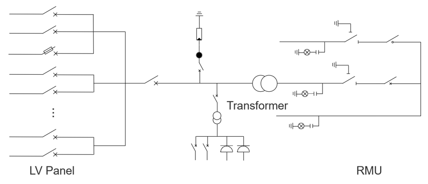
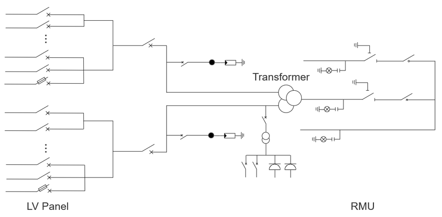
Schematic Diagram:
YBS-3400
YBS-6800
-
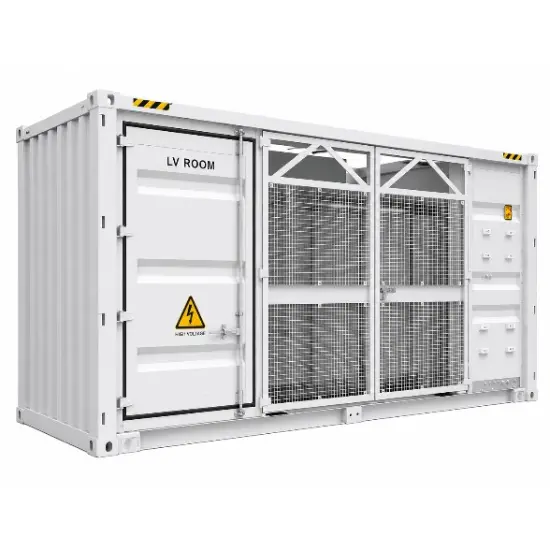
Smart Prefabricated Compact Transformer Station
-
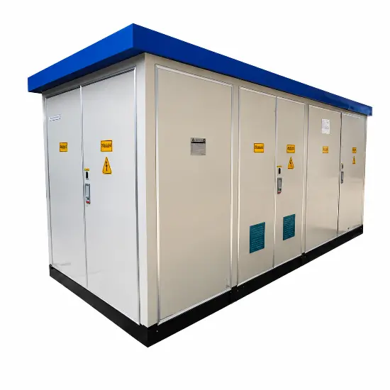
33kV Compact Outdoor Prefabricated Substation
-
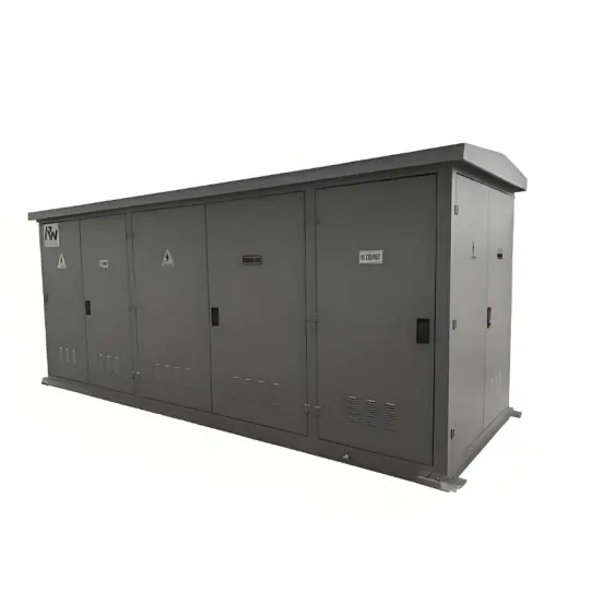
12kV 24kV 36kV Outdoor Prefabricated Transformer Substation
-
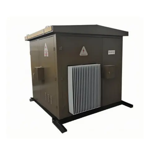
36kV/40.5kV Prefabricated Substation
-
Outdoor Prefabricated Pad-Mounted Transformer 10kV - 40.5kV
-
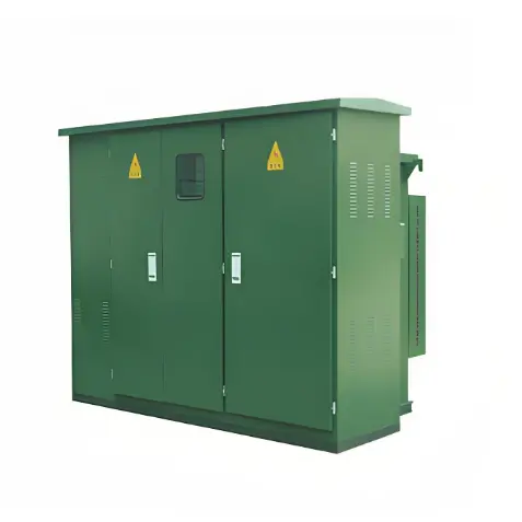
Three Phase Power Distribution Compact Prefabricated Substation 33kV
-
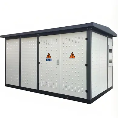
75KVA to 2500KVA Three Phase Substation Ground-Mounted Pad Mounted Transformer
-
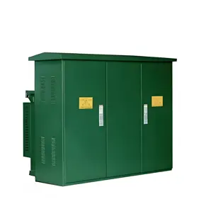
MSUB Series mobile substation
-
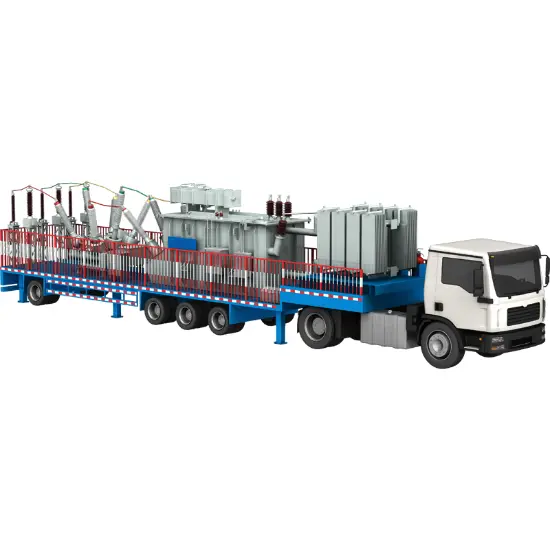
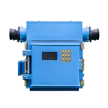
Flameproof and Intrinsically Safe Low-Voltage Protection Box for Mobile Substations in Mining Applications
-
High-voltage Permanent Magnet Mechanism Vacuum Switch for Mining Flameproof Mobile Substations