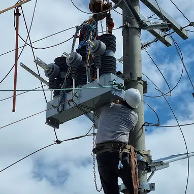
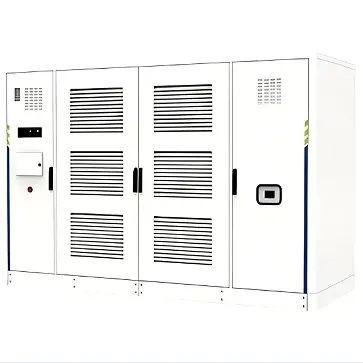
Namibia 33kV 2500kVA PV Transformer Efficiency and Loss Optimization Solution
Namibia 33kV 2500kVA PV Power Plant Step-up Transformer Efficiency and Loss Optimization Solution
Designed for Namibia's extreme high-temperature environments, this solution utilizes next-generation low-loss magnetic materials and optimized winding structures to maximize lifecycle energy efficiency at 50°C ambient temperature.
Applications: Utility-scale solar farms, centralized grid-tied systems
Efficiency Grade: Compliant with IEC 60076-20:2017 Level 2 or higher
Core Objectives: Reduction of No-load Loss (P0), suppression of high-temperature Load Loss (Pk), and minimization of harmonic stray losses.
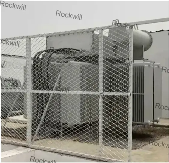
Introduction
In Namibian PV grid-connection projects, the efficiency of step-up transformers directly dictates the final Levelized Cost of Energy (LCOE). With summer ambient temperatures frequently reaching 45°C - 50°C, traditional transformer designs suffer from significantly increased resistive losses. Furthermore, non-sinusoidal currents from inverters introduce harmonic losses that cannot be ignored. This solution focuses on technical strategies to reduce system energy consumption by 15% - 25%, thereby enhancing the ROI of solar assets.
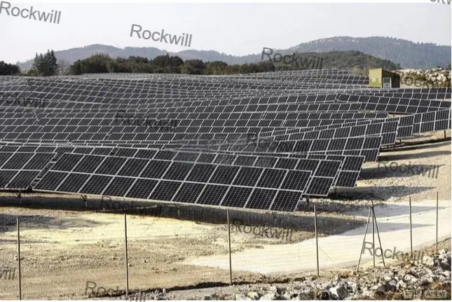
1.Deep Analysis of Efficiency and Loss Pain Points
1.1 Ohmic Loss Surge Due to Extreme High Temperatures
According to the temperature coefficient of resistance for copper/aluminum conductors, an increase in ambient temperature from 20°C to 50°C results in approximately a 10% - 12% increase in effective winding resistance during operation. For a 2500kVA transformer, this means the load loss (Pk) at full capacity will far exceed rated design values, leading to a drop in overall efficiency of over 0.5%.
1.2 Skin Effect Loss Caused by Inverter Harmonics
The 3rd, 5th, 7th, and higher-order harmonics produced by PV inverters increase the AC resistance of windings via the skin effect. Additionally, harmonic leakage magnetic fields induce high-frequency eddy current losses in structural components (such as core clamps and tank walls), causing localized overheating and efficiency degradation.
1.3 Cumulative No-load Loss Under Low Loading Conditions
During night-time and low-irradiance periods, PV transformers operate at no-load or extremely light load. Cumulative no-load loss (core loss, P0) accounts for a significant portion of internal power consumption. If conventional silicon steel is used, the cost of no-load losses over a 25-year lifespan in Namibia represents a massive hidden expense.
1.4 Reactive Power Loss Impacting Grid Power Factor
Excitation and leakage reactance losses within the transformer reduce the power factor at the Point of Common Coupling (PCC). Under NamPower's strict grid codes, insufficient reactive power compensation can lead to penalties or voltage instability.
2. High-Efficiency Design Framework
We follow the "Three Pillars" principle—low-reactance design, premium magnetic materials, and enhanced heat exchange—to ensure optimal performance at a 50°C baseline.
Optimization Dimension |
Core Technical Application |
Expected Outcome |
|---|---|---|
Core Material |
High-permeability Hi-B silicon steel or amorphous alloy |
No-load loss (P0) reduced by 30% - 50% |
Winding Design |
Low current density design (Current Density < 2.0A/mm²) |
Load loss (Pk) at high temp reduced by 15% |
Harmonic Suppression |
Foil winding (LV side) + K-factor certification |
Harmonic stray loss reduced by 40% |
Cooling Efficiency |
Directed oil flow + optimized cooling loop topology |
Operating efficiency maintained above 98.8% |
3. Core Efficiency Solution: 2500kVA High-Efficiency Transformer
3.1 Magnetic Material Selection Comparison
Comparing three core strategies for 24-hour operational characteristics:
3.2 Key Loss Parameters (50°C Ambient Baseline)
Optimized 2.5MVA 33kV parameters according to IEC 60076-20 Level 2 (Reference Temperature 75°C):
Parameter |
Standard Value (Ref) |
Optimized Solution |
Improvement |
|---|---|---|---|
No-load Loss (P0) |
2250 W |
1480 W |
34% ↓ |
Load Loss (Pk) |
22500 W |
18500 W |
18% ↓ |
No-load Current (I0) |
0.8% |
0.15% |
80% ↓ |
Rated Efficiency (Peak) |
98.6% |
99.15% |
0.55% ↑ |
3.3 Specialized Loss Control Technologies
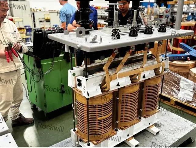
Continuously Transposed Conductors (CTC): CTC is used on the HV side to reduce circulating current losses. Higher winding fill factors allow for a more compact design, reducing leakage flux.
Multi-Step Lap Core Stacking: Utilization of 45° full-mitre joints and non-punching structures significantly reduces excitation current and core loss.
Magnetic and Electric Shielding: Copper shielding is installed inside the tank to intercept leakage flux from high-frequency harmonics, preventing eddy currents in the tank walls.
Proprietary Cooling Topology: For Namibia's peak afternoon temperatures, radiators use a "dual-channel flow" design to ensure the oil-to-ambient temperature gradient remains low, thus limiting winding resistance increase.
4. Typical Cases: Efficiency Gain Analysis
Operational data comparison from typical Namibian projects using high-efficiency transformers:
Project Case |
Environment & Pain Point Context |
Optimization Configuration |
Efficiency & Economic Results |
|---|---|---|---|
Case 1: Erongo 20MW PV Plant |
50°C ambient; traditional efficiency only 98.2%; annual internal consumption 380,000 kWh. |
Level 2 Efficiency 2500kVA Transformer (Hi-B core + CTC windings). |
Comprehensive loss reduced by 22%; annual savings of 84,000 kWh; project ROI increased by 0.6%. |
Case 2: N. Namibia Grid Optimization |
Large night-time I0 caused severe voltage fluctuations at PCC under light load. |
Low magnetic density design; I0 reduced from 1.0% to < 0.2%. |
Reactive loss reduced by 65%; significantly decreased frequency of compensation equipment operation. |
5. Summary of Comprehensive Value
5.1 Economic Value (LCOE Driven)
Direct Power Savings: A single 2500kVA unit saves approximately 20,000 - 30,000 kWh per year.
Lower O&M Costs: Lower operating temperatures slow down insulation oil oxidation and winding relaxation, extending maintenance cycles.
5.2 Technical Value (Grid Compliance)
Grid Stability: Low impedance variation and extremely low no-load current greatly improve voltage stability in weak grid environments.
Environmental Sustainability: Reducing losses directly lowers the carbon footprint, aligning with Namibia's 2030 Energy Strategy.
6. Contact and Consultation (Call to Action)
For detailed technical specifications (Data Sheets) or efficiency ROI simulation reports for your specific PV project in Namibia, please contact our power system experts:
Online Assessment: Visit our official website to submit your project parameters (Voltage, Capacity, Ambient Temp) for a customized low-loss solution.
Appendix: Energy Efficiency Standards
Standard No. |
Description |
Application Scenario |
|---|---|---|
IEC 60076-20 |
Energy efficiency of transformers |
Efficiency grading and assessment |
IEC 61378-1 |
Converter transformers |
Design reference for harmonic handling |
SANS 780 |
Distribution transformers efficiency |
Local Namibian efficiency compliance |
Disclaimer: Loss data in this document is estimated based on 2.5MVA typical models under standard laboratory conditions. Actual data is subject to final technical agreements and factory test reports.