PMU High precision distribution line protection automation system
PMU distribution line protection automation system is a new line distribution automation system for slove present problem especially of earth fault which is base on a Distribution Network Synchronous Phasor Measurement-μPMU.
PMU (phasor measurement unit), A stand-alone device or module. The voltage/current sampling data are all with a BDS/GPS timestamp accurate to US level.
Basic functions: • Phasor: amplitude, phase Angle, • Frequency (f) and Frequency Variation (△f/△t)

μPMU Hardware Architecture Block Diagram
Wide Area Measurement System (WAMS)
• PMU measurements are absolutely synchronized with World
Standard Time (UTC)
• Wide-area measurement synchronization of multiple PMUs
installed in different locations
• Mathematical expression of voltage/current signal:

Overhead Current Sensor i-WCS – Single Channel Current PMU
Solution for distribution network problem which is based on the distribution network PMU and the wide area synchronous phasor measurement technology.
• High precision and high frequency current acquisition
• Wide-area synchronized, power induction
• Live installation, IP67 protection
• Support bi-directional power flow or ring network operation
• 3G/4G/ 5G communication:
a. Periodically report each harmonic
b. Local events trigger the upload data
c. Remote call and test specific moment data

• 1μs Wide-area synchronized
• 12.8kHz Sample frequency
• 60 min Wave record and playback
• 0.5 Measuring accuracy
• 3.5A Full function minimum operating current
Cable Type Current Sensor RCMU – Multichannel Current PMU

RCMU - Underground cable current sensor
• 1μs Wide-area synchronized
• 12.8kHz Sample frequency
• 0.5 Measuring accuracy
• 60 min Data Playback
• 3 current measuring
• Wireless/wired remote transmission
• Collect three-phase current, same as overhead type principle, suitable for ring main unit, switching station, substation.
• Wide area synchronous, induction power, or 24V/48V DC power supply
• Local fault decision algorithm based on current:
a. Short-circuit overcurrent
b. Zero sequence overcurrent
c. Asymmetric phase current
• Wave record called measurement, Support distributed fault location
• Support bi-directional power flow or ring network operation
• 3G/4G/5G or network communication
Bus Collecting Unit BDCU – Single/Multiple Voltage PMU


Indoor type and Outdoor type
• 220V AC/24V DC power supply • Fiber optic, wired, wireless
• IEC 60870-5- 101/104/DNP3 • 300 current sensors can be accessed Voltage Acquisition:
• 1μs Wide-area synchronized
• 1.0 Measuring accuracy
• 12.8kHz Sampling frequency
• 60 min Wave record playback
For single-phase grounding fault with ground current greater than 1A, the detection and positioning accuracy is 100%, with 0 false positives
• Collect zero sequence voltage, start recording of earth fault
• Collect and process the recording wave, and determine the fault comprehensively
• Safe access to the main power distribution station
a. Used as the station grounding insulation monitoring device
b. Used as an in-station grounding insulation monitoring device
c. Do not rely on the master station to complete the fault
The Composition of Intelligent Distribution Network Condition Monitoring System Based on PMU Measurement

Distribution Network Usage Scenarios

Typical Use of PMU - Line Condition Assessment

Typical Use of PMU - Distributed Wave Recording

The recording data of all monitoring points in the line and station are labeled with absolute time at the level of microsecond. Any device can trigger recording when the preset start conditions are met. Provide a "snapshot" of the entire network based on the time callback of any event at any locationup to the recorded data of all sensors. It provides global data for detailed analysis of events and facilitates process inversion, traceability, and early warning of abnormal state, etc.
Typical Use of PMU - Power Quality Monitoring

The sensor can calculate and report harmonics in real time. Based on the wide area synchronous data, various power quality indexes such as three-phase unbalance, grid frequency and frequency
change rate can be calculated, and the pollution source load can be located accordingly.
Typical Use of PMU - Electricity Anti-stealing

According to the user's high-voltage side load data and current waveform, the load characteristics are analyzed and identified, and the terminal user's electrical behavior is monitored, which can be used for remote monitoring and diagnosis of the state of electrical equipment.
Typical Use of PMU: Fault Warning, Traceability and Process Inversion

Warning:
• 2017-10-30 12:15:39:081719, line 115, pole 1# 64#, phase A to ground
• 2017-10-30 12:15:39:093125 , line 117, pole 29#, phase B grounded short circuit, peak flow exceeds 1000A
• 2017-10-30 12:15:39:115468 , Line 115, between poles 1# and 64#, phase A and C short circuit, Peak current at pole 1# exceeds 5000A Field feedback and fault process inversion:
• A car collision accident occurred at pole 52# on line 115
• The inspection found a burn mark in the cable cabinet somewhere behind the pole 29# on line 117
• Speculating that phase A conductor of line 115 falls down the cross arm and causes grounding, and the electric voltage of the non-fault phase increases, which leads to the breakdown of the insulation weak point phase B behind the pole 29# of line 117, forming the short circuit of the phases A and B of different lines and generating the peak current over 1000A
• After tens of milliseconds, the phase C conductor at the pole 52# of Line 115 also falls off the cross arm, causing short circuit of Phase A and C. When the peak of short-circuit current exceeds 5000A, the relay protection at the outlet of the line is operated. After the switch trips, the system runs normally, indicating that the insulation of the original breakdown point of the pole 29# of the line 117 is restored.
Typical Use of PMU: Disconnection grounding fault location

• 2018-10-05,15:27:45:395312, First alarm, the assignment notice is received.
“Allocation notice: 10kV Section 2 Phase A is connected to the ground at 15:29” “Allocation notice: 10kV Section 2 Phase A grounding disappear at 15:47 ”
• Patrol to confirm the break of 127-1-28# of Line 121 branch
• Timely discovery of broken wire contact, to avoid passers-by close to the electric shock. It is speculated that the ground jitter of the broken insulated conductor causes multiple grounding. After the metal core is retracted into the insulation layer, the phase loss operation will result in the bus voltage returning to normal
• During this time, typhoon "Connie" passed through, so it is speculated that the disconnected line was caused by typhoon.
Typical Use of PMU: Big Data + AI Identification Guide to Find Fault Switches
It is Small resistance grounding system, PMU sensor configuration.
whole process of fault identification and confirmation:
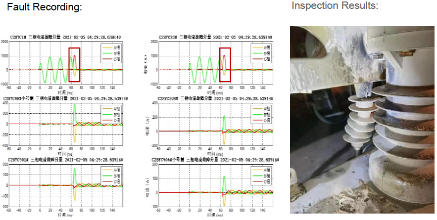
• 2020.11.25 - 2021.2.5, C28YC line had 5 grounding alarms, and all the alarm had the same characteristics, but the fault point could not be found
during on-site inspection.
• The AI identified a match between the characteristics of the second half of the cycle and a type of waveform in the historical database, and deduced that it was a switch defect.
• On February 5, 2021, the on-site personnel had a target in mind and found the switch fault at pole 84.
Typical Use of PMU: Line Insulation Warning - Reason: Meteorological Disaster

Line Neutral Grounding Mode: bus 1 arc suppression coil, bus 2 ungrounded PMU Sensor Layout Details:

System warning times: 13 times
Fault evolution process: on the afternoon of August 13, 2019, there were 13 disturbances, all indicating that they occurred in the same line section. The zero-sequence voltage rises continuously from 20V at the beginning of the warning to 30V at the end. The zero-sequence current increases from 3A to 5A, and the insulation of the line deteriorates. Due to the backlog of emergency repair tasks caused by typhoon one day ago, the priority of early warning and shortage elimination work has been postponed. After 9 hours deterioration into a short circuit, protective action trip, resulting in power failure.
Typical Use of PMU: Line Insulation Warning - Cause: Conflict with Trees

Starting from 21 o 'clock on 2020.5.25, nearly one hundred weak disturbance events were perceived, all of which occurred in the same place.
The damping resistance of the arc suppression coil in the station is seriously heated.
The maintenance personnel patrolled the line according to the warning information.
After clearing the tree barriers and removing the defects, the insulation of about 14 points of the line was completely restored and the system returned to normal.
Typical Use of PMU: Line Fault Warning - Cause: Bird Damage Line Neutral


System warning times: 10
Fault evolution process: From 19:57:41 to 22:48:18 on July 7, 2018, dozens of alarms were raised in the same place.
The time between two faults is getting shorter and the frequency is getting higher, which shows the trend of developing into permanent single-phase grounding faults. At around 10:50, the maintenance personnel manually pulled the switch on the site, destroyed the bird's nest in the fault section, closed the switch to restore power transmission, the fault disappeared.
Typical Use of UCMU : Equipment Failure Warning - Cause: External Force Damage the Cable

Line neutral grounding mode: neutral grounding through arc suppression coil SMS warning times: 1
Fault Evolution Process: Multiple instantaneous grounding occurred since 15:22 on April 24, 2020, and the system pushed multiple warning information. In order to avoid frequent warning of short messages caused by instantaneous disturbance, the system sets three instantaneous grounding times within 20 minutes as the condition for pushing warning short messages. This condition can be improved through the accumulation and learning of big data by setting frequency. By 17:46, it became permanently grounded and lasted for 55 minutes.
Typical Use of PMU: Equipment Failure Warning - Cause: Switchgear Insulation Deterioration

System Warning Times: 4
Fault Evolution Process: During the period of 2020.11.21 to 2020.11.24, there was 4 instantaneous grounding and 1 permanent grounding, and it eventually evolved into a
short circuit fault. The system recorded 5 grounding faults with the same fault interval, imilar waveform and obvious arc pull characteristics, which were judged to be insulation faults at the same location.
For earthing system grounding transformer deatils information > Earthing transformer
More details pls contact us!