Rockwill 30–34.5kV Transformer Anti-Burnout & MV Distribution System Voltage Immunity — An Integrated Solution
1. From Bankruptcy to World-Class Quality: Lessons and the Path to Regeneratio
1.1 Lessons from the Past: The Systemic Crisis Behind a Proactive Recall (2005–2012)
Between 2005 and 2012, a Chinese transformer manufacturer suffered a catastrophic collapse. In an attempt to avert on-site burnout incidents, it proactively recalled over 2,000 transformers already in service and in inventory worldwide, incurring direct losses of nearly RMB 50 million. Despite full compensation and corrective actions, two systemic root causes could not be remedied in the short term:
Widespread under-specification of insulation: To meet low-bid tender requirements across numerous African and Southeast Asian projects, insulation levels were compressed to the IEC minimum of 70 kV pf withstand and 170 kV BIL.
Uncontrolled manufacturing variability: Production relied heavily on manual processes, resulting in unstable partial discharge (PD) control and latent defects that proved impossible to eradicate.
Overwhelmed by the financial and reputational impact of the massive recall, the company declared bankruptcy after 2012.
1.2 Asset Transfer: Experience-Driven Restructuring
Following the bankruptcy, Rockwill acquired the core team of design, process, and quality engineers from the failed manufacturer. These engineers carried with them a complete failure database, first-hand data from thousands of burnout cases, and hard-won lessons in insulation specification — becoming the critical intellectual asset driving Rockwill's transformation. Rockwill's management resolved to use this opportunity to completely rebuild the design and manufacturing system for 30–34.5 kV class products.
1.3 Mandatory Design Standard Uplift: Building an Insulation Firewall
Led by the incoming engineers, Rockwill permanently raised its internal standards well above IEC minimum requirements:
| Application Scenario | Power-Frequency Withstand (PfR) | Lightning Impulse Withstand (BIL) | Note |
|---|---|---|---|
| Global General Baseline | ≥ 80 kV | ≥ 200 kV | Exceeds IEC 60076-3 minimum of 70/170 kV for Um=36kV |
| High Altitude / Weak Grid | ≥ 95 kV | ≥ 250 kV | For altitudes >1000m or systems with single-phase-to-ground operation |
1.4 Digital Manufacturing & Process Standardization: Eliminating Human Error
Failure modes were translated into digitally enforced control points, with process windows locked down through the MES/QMS system.
Coil Winding: MES work orders bind tension curves; sensors monitor in real time; deviation >±5% triggers automatic shutdown.
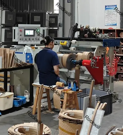
Full-digital CNC Winding Equipment, Closed-loop Regulation on Winding Technical Parameters Based on MES
Lead Exit & Welding: QMS sets welding temperature, duration, and cooling rate. Critical taps undergo X-ray inspection or withstand voltage sampling.
Insulation Layering: Semi-automatic robotic layering with vision system real-time inspection of layer count and tightness, eliminating manual skipped layers.
Vacuum Drying & Oil Filling: MES locks vacuum level, temperature, and duration curves; data uploaded in real time — no manual intervention permitted.
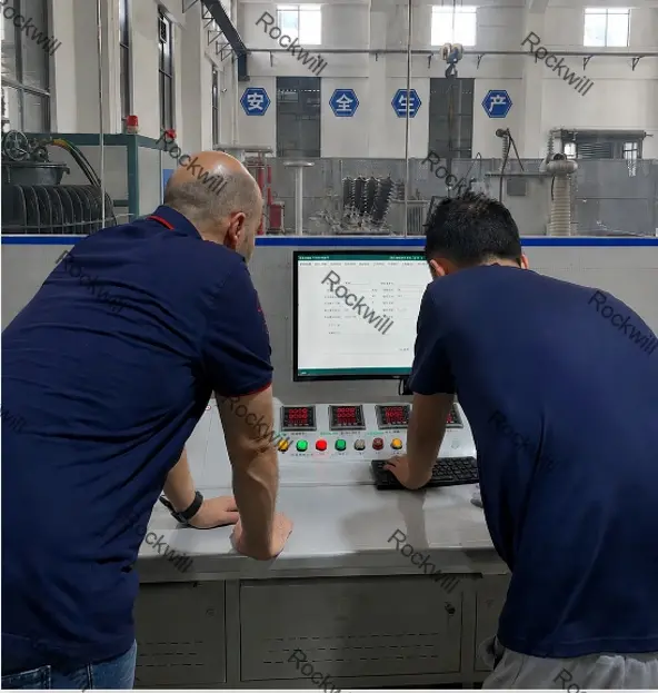
Factory Acceptance Testing: Induced withstand voltage, partial discharge (PD ≤ 50 pC), and no-load over-excitation data are automatically compared; QMS approves release only when all criteria are met.
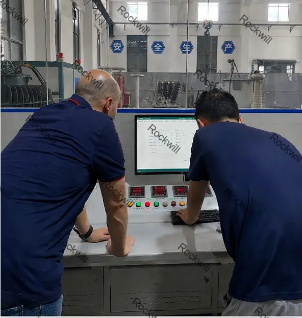
Digitalized Factory Acceptance Test in Lab, Full-test Data Auto-collected & Filed via QMS System
Result: Factory PD pass rate rose from the industry average of 93% to 99.97%, laying the process foundation for zero on-site burnouts.
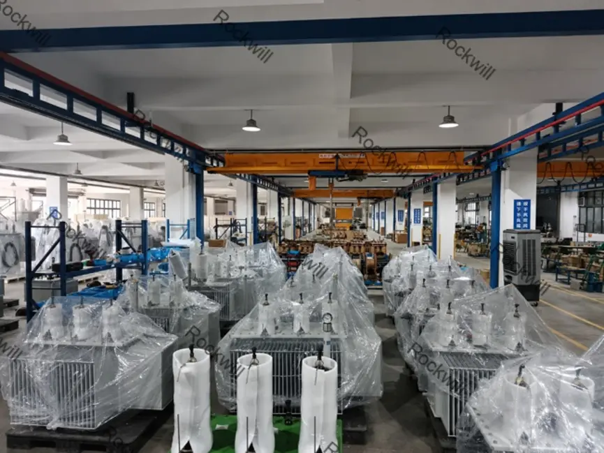
Qualified Finished Transformers After Full-process Control for Warehouse Storage & Stable Large-scale Mass Production
1.5 The Result: Zero Global Burnouts Since 2022
Driven by the dual engine of reinforced design and digital manufacturing, Rockwill's transformers in this voltage class have achieved zero on-site burnouts worldwide since 2022. A representative case is the East African market (Kenya, Tanzania, Ethiopia) — the very region where the predecessor met its downfall.
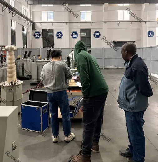
Type Test with On-site Supervision by East African Clients & High-standard Insulation Solution for Project Implementation
Against local tenders still commonly specifying 170/70 kV standards, Rockwill held the line at 200/80 kV minimum.
For plateaus at 1500–2500 m altitude, a mandatory BIL ≥ 250 kV scheme was enforced.
This completely eliminated the combined risk of intermittent arc grounding overvoltage and altitude-driven insulation failure.
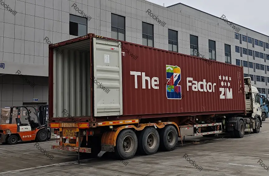
Finished Transformers Pre-assembled in Containers for Shipment & Bulk Export to High-altitude Overseas Projects in Africa
2. System Foundation and Standards Framework
This solution applies to typical nominal system voltages of 33 kV / 34.5 kV, with rated maximum voltage Um = 36 kV / 38 kV, and frequencies of 50/60 Hz.
Core applicable standards:
Transformers: IEC 60076 series (with emphasis on IEC 60076-3 for insulation levels and dielectric tests).
Insulation coordination: IEC 60071, IEEE C57.12.00, IEEE C57.12.90, IEEE C57.12.91, IEEE 1313.
Switchgear: IEC 62271.
Altitude correction: Based on 1000 m reference, strictly per IEC 60071-2 and IEEE 1313 correction factors.
3. Voltage Immunity Design System
3.1 Voltage Disturbance Hazard Matrix
| Disturbance Type | Primary Hazard | Specific Consequence |
|---|---|---|
| Sag / Swell | Motor tripping, contactor dropout | Core saturation (DC bias), inrush current impact |
| Sustained Over/Under Voltage | Core overheating, accelerated insulation aging | Reduced life, induced insulation breakdown |
| Transient Overvoltage | Inter-layer / inter-turn winding breakdown | Direct transformer explosion and fire |
| Harmonic Distortion | Increased stray losses, local overheating | Accelerated oil degradation, bushing damage |
3.2 Passive Immunity: Equipment Withstand Capability
Wide-range voltage regulation: On-load tap changer (OLTC) with regulation range ≥ ±10%.
Flux density control: Core design flux density < 1.7 T at rated voltage. This minimizes over-excitation losses at 110% rated voltage per IEC 60076-1, keeping core heating within acceptable limits under continuous no-load overvoltage operation.
Auxiliary equipment withstand: Critical cooling fans and oil pumps equipped with wide-voltage coils or low-voltage ride-through (LVRT) control.
3.3 Active Regulation: System-Level Voltage Control
AVR & LDC: OLTC-fitted transformers with automatic voltage regulator (AVR) and line drop compensation (LDC).
Dynamic reactive power support: SVC or STATCOM for sub-cycle reactive compensation to suppress flicker and voltage fluctuation.
Load decoupling: Fluctuating loads (rolling mills, arc furnaces, large motors) and sensitive loads on separate busbars, with series reactors or isolation transformers as needed.
3.4 Protection Relay Coordination
Volts-per-Hertz protection (ANSI 24): V/Hz ratio alarm at 1.05–1.1×, time-delayed trip at ≥ 1.2×, preventing over-flux burnout.
Voltage/frequency protection (27/59, 81U/81O): Final defense against system anomalies.
4. Multi-Layer Transformer Burnout Prevention System
4.1 Defense Layer Architecture
| Layer | Core Measure | Target |
|---|---|---|
| 1st | Differential protection (87T) + DGA online monitoring | Inter-turn faults, core multi-point grounding |
| 2nd | Heavy gas relay + sudden pressure relay (63) | Fast trip for internal severe faults |
| 3rd | Overcurrent (50/51) + zero-sequence (50N/51N) | External faults and backup protection |
| 4th | Winding hot-spot / thermal model (49T) | Overheating and insulation aging |
| 5th | Surge arrester + anti-ferroresonance | Overvoltage breakdown |
| 6th | Pressure relief valve + blast vent | Physical explosion mitigation |
4.2 Key Protection Device Configuration
Differential protection (87T): Required for ≥ 5 MVA or critical transformers. Must include phase compensation and second-harmonic blocking (anti-inrush).
Gas relay protection: Alarm on light gas, trip on heavy gas. Must never be bypassed or substituted.
Temperature protection: Per IEC 60076-7 thermal model or fiber-optic thermometry. Winding hot-spot alarm at 110°C for oil-immersed; cooling failure logic must initiate load reduction or trip.
Zero-sequence protection: Precisely set according to neutral earthing method (resistance / Petersen coil / unearthed). Guard against intermittent arc overvoltage.
4.3 Insulation Coordination & Overvoltage Protection
Surge arrester selection: For 34.5 kV systems, select arrester with Uc ≥ 27–30 kV. Residual voltage must be 15–20% below transformer BIL. Install close to the transformer HV bushing; ground terminal directly connected to the transformer earth grid.
Anti-resonance measures: Install ferroresonance damping resistors on the primary side of electromagnetic VTs, or use electronic VTs, to avoid ferroresonance-induced overvoltage.
4.4 Structural Burnout-Resistant Design
Materials: Oxygen-free electrolytic copper windings and high-density insulation paper.
Short-circuit withstand: Strictly verified per IEC 60076-5 for both thermal and dynamic short-circuit capability.
Sealing: Fully welded or high-reliability sealed construction to prevent moisture ingress from breathing.
5. High-Altitude Design Adaptability (1000 m – 5000 m)
5.1 Insulation Level Correction
For altitudes > 1000 m, withstand voltage correction per IEC 60071-2:
| Altitude | Recommended BIL (Um=36 kV) | Strategy |
|---|---|---|
| 1000 – 2000 m | ≥ 200 kV | Maintain high standard baseline |
| 2000 – 3500 m | ≥ 217 – 230 kV | Reinforced external insulation or upgrade to 40.5 kV class equipment |
5.2 External Insulation & Derating
Air Clearances & Creepage: Minimum electrical clearances scaled per altitude. Creepage distance selected per IEC 60815 for high pollution class (d/e), actual creepage ≥ 25–31 mm/kV.
Temperature Rise Derating:
Oil-immersed: For every 500 m above 1000 m, temperature rise limit reduced by 1%.
Dry-type: For every 500 m above 1000 m, temperature rise limit reduced by 2.5%.
At 4000 m, typical derating is 10–15%, or cooling capacity must be increased.
6. Global Application Design Specification (Rockwill Execution Standard)
To ensure "zero burnout" is achieved, every project must comply with the following checklist:
6.1 Mandatory Pre-Design Data Collection
Altitude, extreme temperatures, pollution class, thunderstorm days, earthing method, and historical voltage fluctuation records must be obtained.
6.2 Insulation Selection Red Line
The 170 kV / 70 kV standard is strictly prohibited as a baseline solution. Manufacturing standards shall enforce BIL ≥ 200 kV / AC ≥ 80 kV. High-altitude projects shall use corrected values (e.g., 250 kV class).
6.3 Transformer Manufacturing Standards
Partial discharge: ≤ 50 pC.
MES data: Winding tension curves, vacuum drying profiles, and test data fully traceable.
OLTC and automatic voltage regulation mandatory. Temperature rise designed per high-altitude derating rules.
6.4 Switchgear & System
Air clearances and creepage distance subject to altitude correction.
Current carrying capacity derated by 10–20%. GIS or reinforced insulation switchgear preferred.
6.5 Protection Configuration (Complete Set)
Mandatory: 87T, 63, 49T, 24, 50/51/50N.
Surge arrester protection margin ≥ 20%.
6.6 Power Quality Management
SVC/STATCOM configured per short-circuit capacity with appropriate voltage dead-band settings.
6.7 Factory Acceptance Testing (FAT)
Induced withstand voltage and PD tests mandatory for witness.
QMS process record review required.
High-altitude insulation correction calculation report or type test report to be delivered.
Closing
The differentiation of Rockwill's 30–34.5 kV transformer design, manufacturing practice, and accompanying MV system solution does not lie in the mere stacking of parameters. It is rooted in transforming one industry-level bankruptcy lesson into three non-negotiable engineering principles: an insulation baseline far exceeding IEC minimums, digital processes that eliminate manufacturing variability, and a closed-loop design that integrates insulation coordination with protection systems. Only through a system-level approach can the risk of transformer burnouts be reliably eliminated.