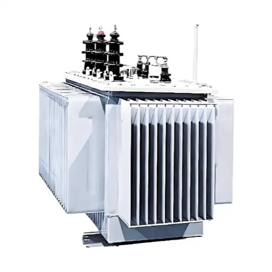
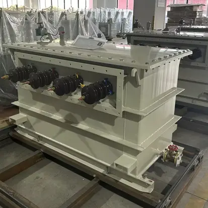
China Oil Immersed Grounding Transformer Manufacturer 15kV-35kV
Key attributes
| Brand | ROCKWILL |
| Model NO. | China Oil Immersed Grounding Transformer Manufacturer 15kV-35kV |
| Rated voltage | 33kV |
| Phases | Three-phase |
| Frequency range | 50/60Hz |
| Series | JDS |
Description
Product Showcase Video
Key Features
- Medium-Voltage Neutral Grounding :Provides an artificial neutral point for ungrounded or delta-connected systems, enabling connection of arc suppression coils or neutral grounding resistors.
- Optimized Z-Type Winding :Zigzag (ZN) winding configuration delivers low zero-sequence impedance, ensuring efficient fault current path and sensitive relay protection.
- Oil-Immersed Fully Sealed Construction:Durable sealed tank design with mineral oil insulation ensures long service life, strong overload capacity, and maintenance-free outdoor operation.
- Flexible Cooling Options :Available with ONAN, ONAF, AN, or AF cooling systems to match application load profiles and ambient conditions.
Which Voltage Class Fits Your Grid?
| Your Grid Situation | Recommended Class (Um) | Typical Role |
|---|---|---|
| Rural / small industrial feeder | 17.5 kV (15 kV system) | Local neutral for arc-suppression coil |
| Regional distribution substation | 24 kV (22 kV system) | NGR grounding on delta source |
| Solar / wind collector system | 36 kV (30 / 33 kV system) | Sensitive earth-fault detection |
| Industrial plant incoming line | 40.5 kV (35 kV system) | High-reliability utility grounding |
How the Neutral Actually Forms — in Three Steps
- Normal operation — the ZN (zigzag) winding draws almost no current, so the transformer stays effectively idle.
- Earth fault appears — the same winding suddenly presents a very low zero-sequence impedance, opening a clean return path through the neutral.
- Protection acts — fault current stays within your relay settings, arc-grounding overvoltage is damped, and the healthy phases are protected.
Anatomy of the Sealed Oil Design
- Optimized ZN zigzag winding — low zero-sequence impedance (tolerance ≤ ±10 %) for sensitive, selective tripping.
- Hermetically sealed welded tank — mineral-oil insulation isolated from air: no moisture, no oxidation, no oil sampling, maintenance-free outdoor duty.
- Strong overload headroom — generous thermal margin for the short-time fault duty (10 s / 30 s / 60 s).
- Adaptive cooling — ONAN / ONAF / AN / AF, matched to load profile and site climate.
- Dual-purpose option — an optional auxiliary winding doubles the unit as station-service supply.
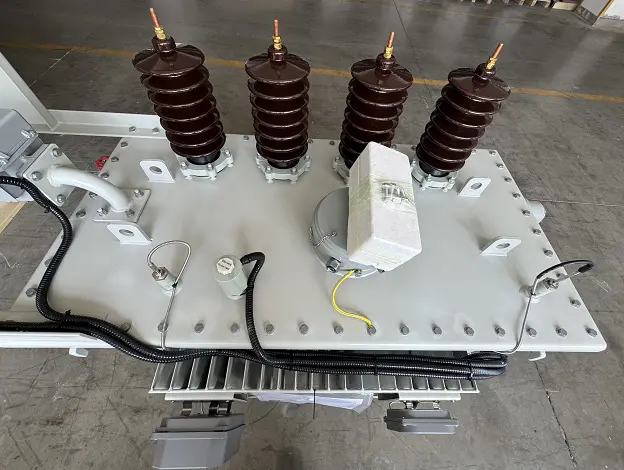
Technical Parameters
| Parameter | Value |
|---|---|
| Highest voltage for equipment (Um) | 17.5 / 24 / 36 / 40.5 kV |
| Rated frequency | 50 / 60 Hz |
| Number of phases | Three |
| Connection group | ZN (zigzag) |
| Rated neutral current | Up to 3000 A |
| Rated short-time duration | 10 s / 30 s / 60 s (customizable) |
| Zero-sequence impedance (Zo) | Per project specification (tolerance ≤ ±10 %) |
| Cooling method | ONAN / ONAF / AN / AF |
| Insulation medium | Mineral oil |
| Auxiliary winding | Optional |
| Ambient temperature | –40 °C to +40 °C |
| Installation | Indoor or outdoor |
| Enclosure options | IP-rated cabinet; optional CT, VT, or isolation switch |
Insulation Levels by Voltage Class
| System Voltage | Um (kV) | PF (kV) | LI (kV) |
|---|---|---|---|
| 15 kV | 17.5 | 38 | 95 |
| 22 kV | 24 | 50 | 125 |
| 30 kV | 36 | 70 | 170 |
| 33 kV | 36 | 70 | 170 |
| 35 kV | 40.5 | 95 | 200 |
Applications
- Medium-voltage distribution network neutral grounding
- Wind farm and photovoltaic power station grid connection
- Industrial and mining enterprise power distribution
- Utility substations and switching stations
- Urban power grid upgrading and renovation
Tune It to Your Project
Solutions for Earthing Transformer Manufacturer
-
 Southeast Asia Power Solutions: Zig-Zag Grounding Transformer for Cost-Effective & Reliable Grid StabilitySoutheast Asia Power Solutions: Zig-Zag Grounding Transformer for Cost-Effective & Reliable Grid StabilityZig-Zag transformers (also known as Z-connected grounding transformers) offer significant advantages in Southeast Asian power systems due to their unique design, which addresses tropical climates, grid structures, and development needs. Below is an analysis of their core benefits and application scenarios:I. Cost Efficiency & Space Optimization Low-Cost SolutionSimplified constructio
-
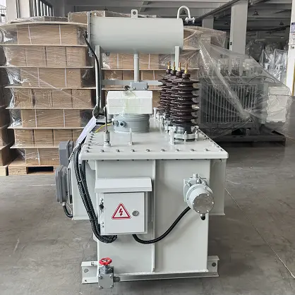 Oil-Immersed Grounding Transformer for Chile’s Mining and Renewable Energy NetworksChile has one of the more developed power standards systems in South America, with a grid architecture shaped by its unique geography. The northern mining and renewable energy hubs, such as the Atacama Desert PV clusters, commonly operate at 34.5kV or 23kV medium-voltage levels, under demanding environmental conditions. To address high altitude, high salinity, intense solar radiation and long-distance transmission, Rockwill provides customized oil-immersed grounding transformer solutions. This s
-
 Earthing Transformer Solution for Egypt’s Distribution NetworkAs a major economy in North Africa, Egypt’s power system is facing growing pressure from rapid urbanization and industrialization. In core cities such as Cairo and Alexandria, as well as in the Suez Canal Economic Zone, the distribution network relies heavily on cable systems with high capacitive earth fault currents. Many areas are also located near desert environments, where operating conditions are harsh.1. Challenge AnalysisTechnical challengesHigh wind-blown sand, large day-night temperatu
Documentation Resource Library Earthing Transformer Manufacturer
Certifications Earthing Transformer Manufacturer

FAQ for Earthing Transformer Manufacturer
The IEC cooling code naming rule uses the first letter to identify the internal cooling medium. ONAN and ONAF start with “O”, which means mineral oil is the primary internal coolant and are the standard options for oil‑immersed units.
AN means air natural cooling and AF means air forced cooling, and these two codes are originally defined for dry‑type transformers without liquid insulation.
For oil‑immersed earthing transformers, AN and AF are not the primary design codes; they are only listed as alternative references for special compact cabinet‑integrated layouts where air convection dominates the thermal dissipation.
When placing an order, ONAN or ONAF should be selected as the formal cooling classification to avoid confusion in tender documents and grid approval files.
Earthing transformer follows short‑time fault‑duty design philosophy, fundamentally different from conventional power transformer rated for continuous load. Its core design basis is short‑time neutral fault current together with fault clearing duration, rather than continuous power‑transfer capacity.
If users specify capacity according to continuous kVA of regular power transformer, the result will be either over‑sized with unnecessary high purchase cost and larger footprint, or wrong thermal design which cannot withstand required I²t fault energy during real single‑phase earth fault.
Proper specification work should start from system capacitive earth‑fault current, then derive required short‑time rating, instead of copying power‑transformer selection logic.
In general, parallel‑operation of multiple zig‑zag earthing transformers on one MV busbar is not recommended unless specially engineered. Each unit has its own manufacturing tolerance of zero‑sequence impedance. When paralleled, unbalanced zero‑sequence circulating currents will appear between transformers even without actual earth fault.
These circulating currents produce extra heating loss and may trigger mis‑operation of zero‑sequence protection relays. If project conditions really require parallel deployment, every unit’s zero‑sequence impedance tolerance, winding polarity and phase‑angle characteristics must be strictly matched, and detailed calculation on circulating‑current magnitude needs to be completed at design phase.
Most standard projects adopt one single earthing transformer for each isolated bus‑section as preferred solution.
Even though the optional auxiliary winding can deliver station‑service power under normal operating condition, its priority ranks below the main neutral‑earthing protection function.
During single‑phase earth‑fault event, large zero‑sequence currents flow through primary zig‑zag windings, which will induce considerable over‑voltage and over‑current on secondary side. Under fault condition, it is not allowed to keep critical station‑service loads running continuously via this auxiliary winding.
Project design should avoid relying entirely on the earthing‑transformer secondary winding for essential uninterruptible auxiliary power. Independent station‑service transformer or UPS power source shall be configured for important loads that cannot lose supply during earth‑fault incidents.
Its loss characteristics are highly related to operating characteristics: ① No-load loss refers to the iron loss (core hysteresis and eddy current loss) during normal operation. Due to long-term no-load/light load status, it is the main operating loss; ② Load loss refers to the copper loss (winding resistance loss) during faults, which is only generated during short-time faults and accounts for a very low proportion. The impact on operating costs needs to be divided by scenarios: For low-voltage and medium-voltage distribution networks (earthing transformers operate for a long time), the impact of no-load loss is obvious, and models with low no-load loss (such as national standard level 1 energy efficiency) should be preferred during selection; for high-voltage/extra-high voltage systems (earthing transformers work for a short time during faults), the proportion of no-load loss is small, and fault tolerance performance can be prioritized. Overall, its annual loss is much lower than that of ordinary power transformers, and the operating cost is relatively low
-
Oil-Immersed Neutral Grounding Transformer OEM ODM 17.5kV-40.5kV
-
China Oil Immersed Grounding Transformer Manufacturer 15kV-35kV
-
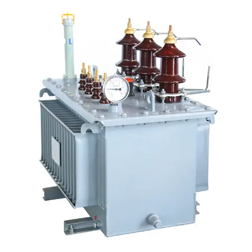
Three Phase Zig-Zag Type Oil-Immersed Earthing Transformer source manufacturer 34.5kV 35KV 88kV 110kV
-
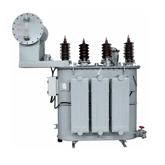
Customized Neutral Grounding Transformer Manufacturer-33kV
-
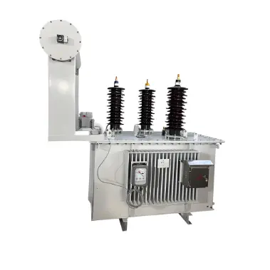
Three Phase Neutral Grounding Transformer Supplier 15kV-36kV
-
IEC Oil-Immersed Zigzag Earthing Transformer Manufacturer-11kV to 35kV

-
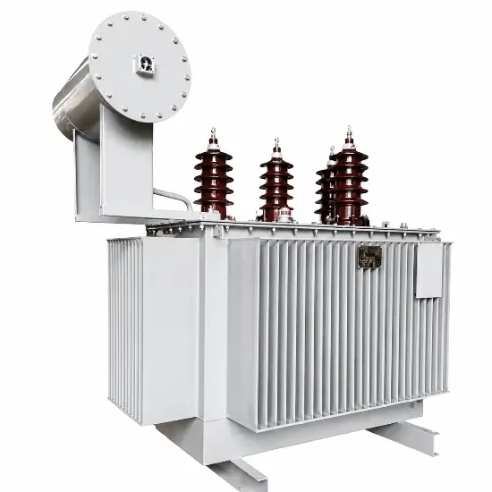
Three Phase Z-type Oil-Immersed Earthing Transformer OEM China 10kV-35kV
-
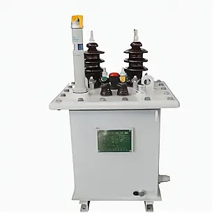
Single Phase Compact Oil Immersed Power Distribution Transformer 11kV
-
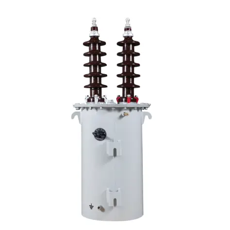
Single Phase Oil Immersed Power Distribution Transformer1250kVA/20kV
-
Oil-immersed amorphous alloy distribution transformer 35kV