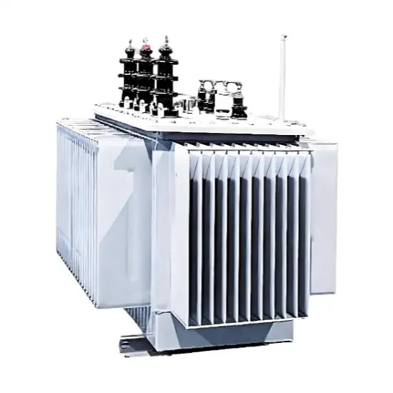
Oil-Immersed Neutral Grounding Transformer OEM ODM 17.5kV-40.5kV
Key attributes
| Brand | ROCKWILL |
| Model NO. | Oil-Immersed Neutral Grounding Transformer OEM ODM 17.5kV-40.5kV |
| Rated voltage | 33kV |
| Rated frequency | 50/60Hz |
| Rated capacity | 800kVA |
| Series | JDS |
Description
Why a Z-Type Earthing Transformer Is Needed?
Product Showcase Video
Key Features
-
Stable Artificial Neutral Point:Provides a reliable neutral for ungrounded or resistance-grounded MV systems, enabling connection of neutral grounding resistors or arc suppression coils.
-
Optimized Z-Type Zigzag Winding:The ZN winding configuration delivers low zero-sequence impedance, ensuring an efficient fault current path and sensitive relay protection.
-
Fully Sealed Oil-Immersed Construction:A durable sealed mineral-oil tank isolates the insulation from air and moisture, improving service life, overload capability, and outdoor reliability.
-
Customizable Capacity Range:Rated capacity from 30 kVA to 3000 kVA, configurable to match system grounding requirements.
-
Optional LV Auxiliary Winding:An integrated secondary winding at 200–440 V can be provided for station service power supply.
-
IEC-Compliant Design:Manufactured in accordance with IEC 60076-6, IEC 60076-1, and ISO 9001 requirements.
Technical Parameters
| Parameter | Value |
|---|---|
| Highest voltage for equipment (Um) | 17.5 / 24 / 36 / 40.5 kV |
| Rated frequency | 50 / 60 Hz |
| Number of phases | Three |
| Connection group | ZN (zigzag) |
| Rated capacity | 30 – 3000 kVA (customizable) |
| Winding material | Copper or aluminum (customizable) |
| Cooling method | ONAN (oil natural air natural) |
| Insulation medium | Mineral oil |
| Auxiliary winding | Optional (200 V – 440 V) |
| Installation | Indoor or outdoor |
| Standards compliance | IEC 60076-6, IEC 60076-1, ISO 9001 |
Insulation Levels by Voltage Class
| System Voltage | Um (kV) | PF (kV) | LI (kV) |
|---|---|---|---|
| 15 kV | 17.5 | 38 | 95 |
| 20 kV | 24 | 50 | 125 |
| 22 kV | 24 | 50 | 125 |
| 30 kV | 36 | 70 | 170 |
| 33 kV | 36 | 70 | 170 |
| 35 kV | 40.5 | 95 | 200 |
Environmental Conditions
| Max ambient air temperature | +40°C |
| Max 24h average ambient air temperature | +35°C |
| Min ambient air temperature | -25°C |
| Altitude | ≤ 1000 m |
| Max relative humidity (24h average) | ≤ 95% |
| Max relative humidity (1 month average) | ≤ 90% |
| Max water vapor pressure (24h average) | 2.2 kPa |
| Max water vapor pressure (1 month average) | 1.8 kPa |
| Solar radiation | ≤ 1000 W/m² |
| Pollution level | II |
Applications
- Medium-voltage distribution network neutral grounding
- Industrial plant power distribution with resistance-grounded systems
- Utility substations and switching stations
- Commercial and institutional building power systems
- Renewable energy power collection and grid connection
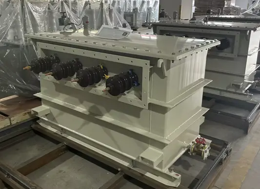
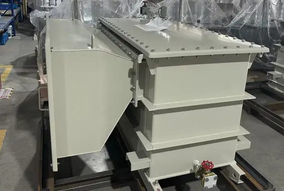
Manufacturing Capabilities
Request a Protection-Ready Quote
Solutions for Grounding Transformer OEM
-
 Southeast Asia Power Solutions: Zig-Zag Grounding Transformer for Cost-Effective & Reliable Grid StabilitySoutheast Asia Power Solutions: Zig-Zag Grounding Transformer for Cost-Effective & Reliable Grid StabilityZig-Zag transformers (also known as Z-connected grounding transformers) offer significant advantages in Southeast Asian power systems due to their unique design, which addresses tropical climates, grid structures, and development needs. Below is an analysis of their core benefits and application scenarios:I. Cost Efficiency & Space Optimization Low-Cost SolutionSimplified constructio
-
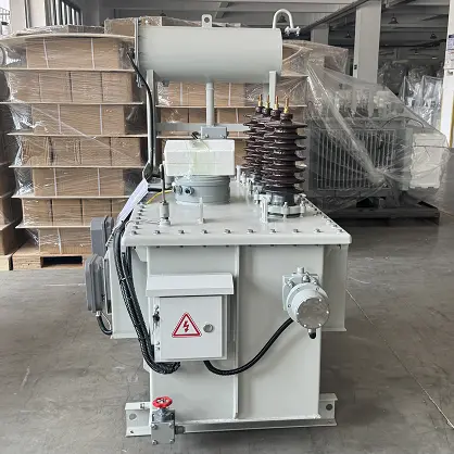 Oil-Immersed Grounding Transformer for Chile’s Mining and Renewable Energy NetworksChile has one of the more developed power standards systems in South America, with a grid architecture shaped by its unique geography. The northern mining and renewable energy hubs, such as the Atacama Desert PV clusters, commonly operate at 34.5kV or 23kV medium-voltage levels, under demanding environmental conditions. To address high altitude, high salinity, intense solar radiation and long-distance transmission, Rockwill provides customized oil-immersed grounding transformer solutions. This s
-
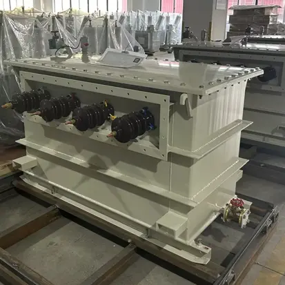 Earthing Transformer Solution for Egypt’s Distribution NetworkAs a major economy in North Africa, Egypt’s power system is facing growing pressure from rapid urbanization and industrialization. In core cities such as Cairo and Alexandria, as well as in the Suez Canal Economic Zone, the distribution network relies heavily on cable systems with high capacitive earth fault currents. Many areas are also located near desert environments, where operating conditions are harsh.1. Challenge AnalysisTechnical challengesHigh wind-blown sand, large day-night temperatu
Documentation Resource Library Grounding Transformer OEM
Certifications Grounding Transformer OEM

FAQ for Grounding Transformer OEM
Upon arrival, the first step is visual inspection for tank deformation, paint damage, oil leakage on welds, flanges and valve connections.
The nameplate data should be cross-checked against the technical datasheet, including winding material, rated neutral current, zero-sequence impedance tolerance, auxiliary winding voltage and cooling method.
The oil level gauge reading and sealing status need confirmation. Before energization, routine field tests are recommended: winding resistance, vector group verification, insulation resistance and dielectric loss measurement.
If it is equipped with an auxiliary winding, no-load voltage test should be carried out to verify the low-voltage output. All factory test certificates shall be kept for local grid inspection and audit.
Yes, it is fully suitable for standalone switching stations and distribution switching points with no generators. Switching stations often split long overhead cable feeders and require a neutral point for the whole section of network to detect earth faults and suppress transient overvoltage.
Even without onsite power generation, the ungrounded feeder section still has distributed capacitive earth‑fault current, which needs a dedicated zigzag earthing unit to establish a neutral reference.
The selection process follows the same principle: calculate total feeder capacitance, define target fault current and protection clearing time, then confirm neutral current rating and short‑time withstand capacity.
Current transformers and voltage transformers installed together with the earthing transformer supply measured signals for zero‑sequence protection relays, fault recording and insulation monitoring devices. The isolation switch provides a visible break point for safe isolation during maintenance.
When these components are factory‑integrated inside an IP‑rated cabinet, all wiring, polarity checks and insulation tests are finished before shipment. This reduces site wiring errors, cuts field commissioning time and removes the risk of mismatched polarity between transformer and protection sensors.
It also simplifies civil layout, as contractors receive a single pre‑tested unit rather than multiple separate pieces of equipment that need to be aligned on site.
Solar and wind farm collection networks are mostly ungrounded or low‑current grounded medium‑voltage systems with large distributed capacitance to earth. A zigzag winding provides a dedicated low‑impedance zero‑sequence path, which enables reliable earth fault detection and controlled fault current.
Unlike wye‑delta earthing schemes, the zigzag design presents high impedance to balanced positive‑sequence operating currents under normal operation, so it consumes very little no‑load magnetizing loss and does not disturb normal power delivery.
It can work smoothly with either resonant arc suppression coils or resistive grounding cabinets, adapting to different grid codes issued by power utilities for renewable interconnection.
Compact structure and flexible neutral‑current rating also suit the limited footprint inside wind and solar collector substations.
Marine/offshore transformers demand salt-spray-resistant insulation, compact oil-free construction, reinforced vibration-proof design (meeting IEC 60076-5 Class 3), customized shipboard voltages/frequencies (e.g., 6.6kV/60Hz) with auxiliary windings for onboard loads, and natural air cooling (KNAN) for reliable enclosed-cabin operation.
-
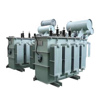
Oil-Immersed Neutral Grounding Transformer OEM ODM 17.5kV-40.5kV
-
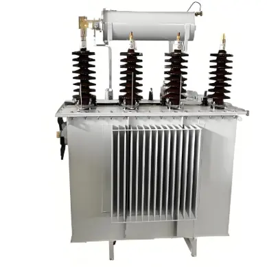
China Oil Immersed Grounding Transformer Manufacturer 15kV-35kV
-
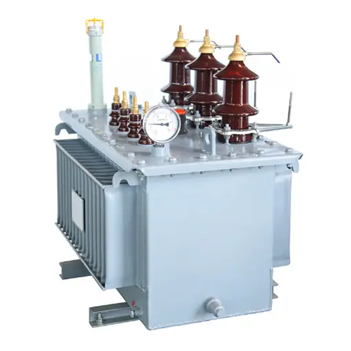
Three Phase Zig-Zag Type Oil-Immersed Earthing Transformer source manufacturer 34.5kV 35KV 88kV 110kV
-
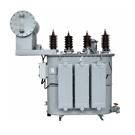
Customized Neutral Grounding Transformer Manufacturer-33kV
-
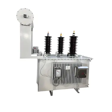
Three Phase Neutral Grounding Transformer Supplier 15kV-36kV
-
IEC Oil-Immersed Zigzag Earthing Transformer Manufacturer-11kV to 35kV

-
Three Phase Z-type Oil-Immersed Earthing Transformer OEM China 10kV-35kV
-
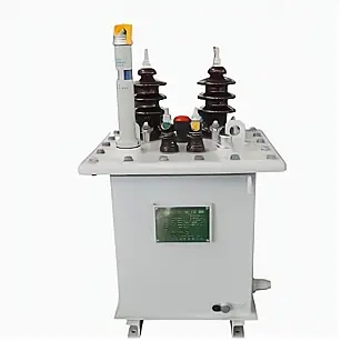
Single Phase Compact Oil Immersed Power Distribution Transformer 11kV
-
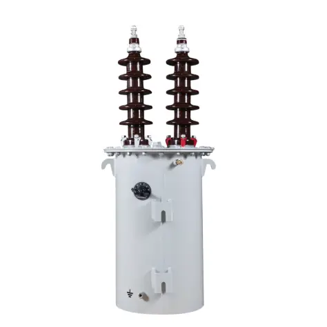
Single Phase Oil Immersed Power Distribution Transformer1250kVA/20kV
-
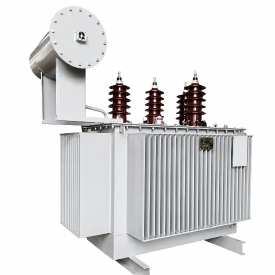
Oil-immersed amorphous alloy distribution transformer 35kV